Behind the Build · 26 March 2026
Behind the Build: Why Quality Starts with the Drawings
Architectural drawings describe intent. Construction quality depends on a much larger set of drawings that describe exactly how the building goes together.
Most people picture a set of architectural drawings — plans, elevations, sections — and assume that is what a builder works from. It is only the beginning. A building that goes together cleanly needs its junctions, services and tolerances resolved on paper, before anyone is standing on site with a decision to make and a schedule to keep.
The drawing set, in plain terms
Architectural drawings describe the spaces: dimensions, levels, openings, finishes, the relationship between rooms.
Structural drawings describe how the building stands up: foundations, columns, beams, slabs, reinforcement, and the loads each element carries. These are produced by engineers against the ground conditions and the specific building.
MEP drawings describe the mechanical, electrical and plumbing systems: drainage runs and falls, water supply, electrical circuits and distribution, air conditioning equipment, condensate drainage, ventilation, and where every one of these things physically sits.
Construction details are the drawings buyers never see and quality depends on: the enlarged sections showing exactly how a window meets a wall, how waterproofing turns up at a threshold, how a roof meets a parapet, how a shower floor falls to a drain.
Why detail drawings exist
Buildings fail at junctions. Water finds the place where two materials meet. Heat and movement concentrate at edges. Services conflict where they cross. A drawing set that stops at the general arrangement leaves those junctions to be resolved by whoever is on site that week.
Take one ordinary example: a sliding door onto a terrace. The detail has to resolve the structural opening, the door frame fixing, the waterproofing membrane and where it terminates, the threshold drainage channel, the finished floor levels inside and out, the movement joint, and the sealant. Resolved on paper, it is a twenty-minute drawing. Unresolved, it becomes an improvised solution and, often, the place water eventually gets in.
Coordination: the part that saves the most
Coordination means checking that the structural, architectural and MEP drawings describe the same building. Common conflicts are unremarkable individually and serious collectively:
- A drainage run that needs a fall, crossing a structural beam that cannot be cut.
- A downlight positioned where a duct is already running.
- A wall too thin for the services intended to sit inside it.
- A window head at the exact level of a structural element.
- Ceiling voids too shallow for the equipment specified.
Each conflict has only two possible resolution points: on paper, or on site. On paper it costs drawing time. On site it costs programme time, and the fix is usually a compromise — a dropped ceiling, a boxed-in duct, a slightly moved opening, a chased structural element that should not be chased.
Dimensions and tolerances
Tolerance is the allowable variation between a drawing and the finished work. It matters most where materials are manufactured off-site: joinery, stone, glazing, sanitaryware. If the opening is 15mm out of square and the tolerance is 5mm, something has to be cut, packed or disguised.
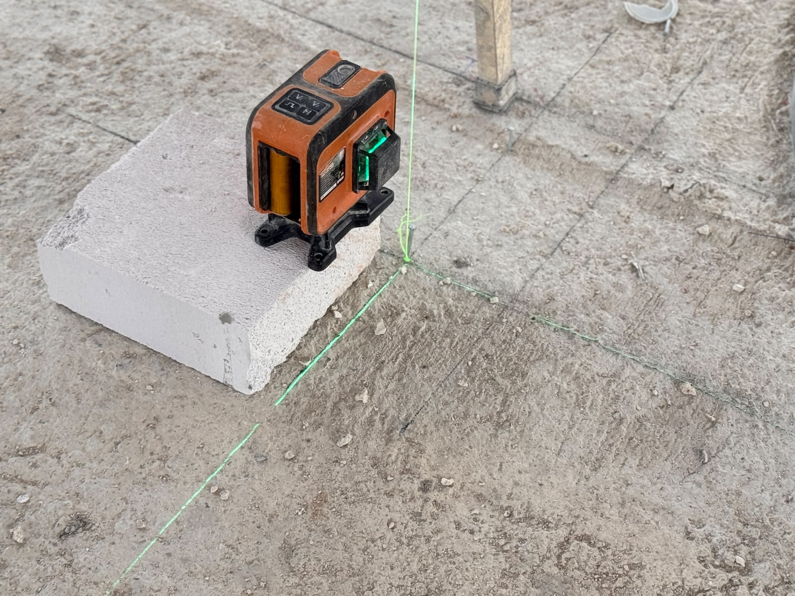
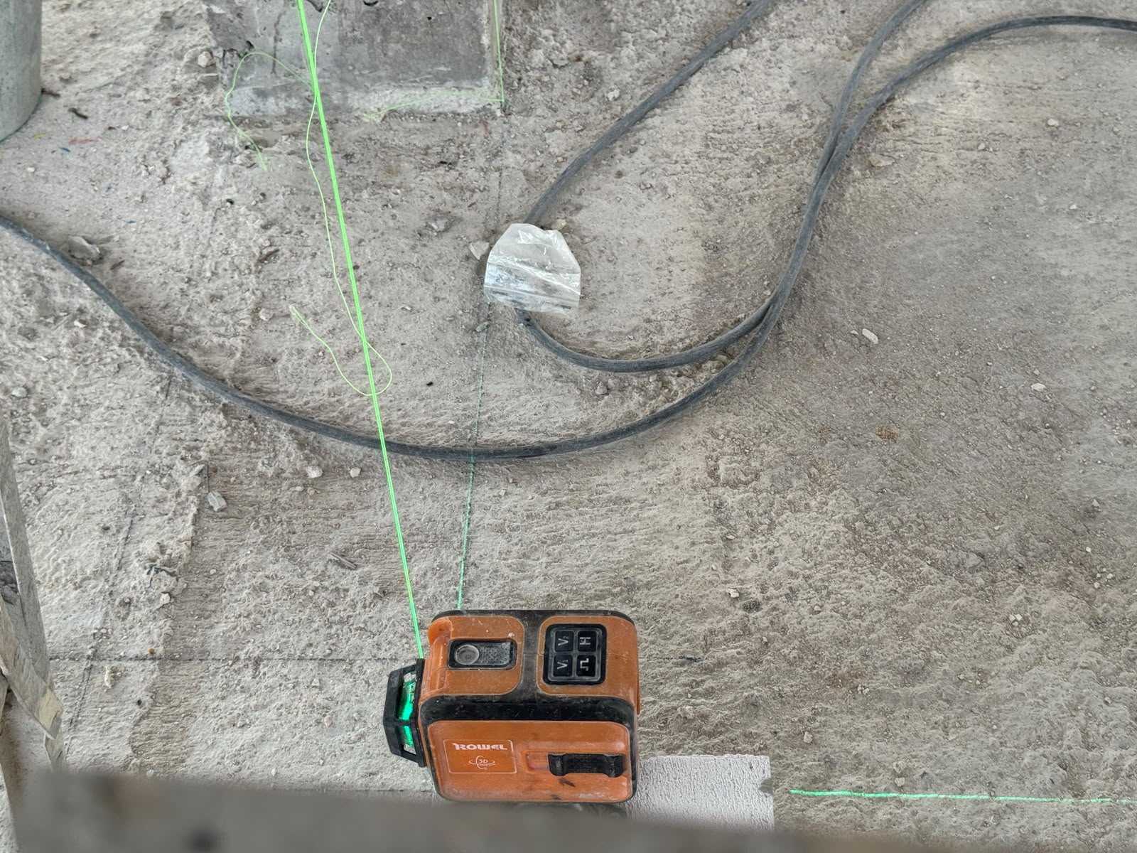
Setting out dimensions, structural grid lines and finished floor levels stated clearly on drawings are what keep tolerances under control. So does checking the built work against those dimensions before the next stage begins.
Waterproofing needs its own drawings
Waterproofing is a system, not a product, and systems need to be drawn. The critical information is not "apply membrane" but where the membrane starts and stops, how far it turns up walls, how it is dressed into drains, how it is protected during subsequent work, and how it meets thresholds and penetrations.
Bathrooms, terraces, planters, roofs and pool surrounds are the places where this either works or quietly does not. None of it is visible after tiling.
Ceilings, lighting and services
Reflected ceiling plans coordinate lighting, air conditioning outlets, sprinklers where required, speakers, access panels and structure. Without them, layouts are resolved by the electrician after the ceiling frame is up — which is why lights are sometimes not quite centred, or a grille lands awkwardly beside a downlight.
From coordination to construction
A coordinated drawing set gives each trade a common technical reference and reduces the number of decisions left to improvisation on site. It should remain controlled as revisions are issued, with superseded information removed from use.
Drawings establish the intended standard; site inspections verify that the built work follows it. Read how quality is controlled on a construction site for the stages that follow.
Published by Dreamvista Development
Developer of The Vista Hua Hin
Discover The Vista Hua Hin
Explore the residences, current availability and the latest opportunities at The Vista Hua Hin.